Generative design ◆ Topology optimisation ◆ Self-balancing robot ◆ University of Toronto ◆ SPIE ACAIB 2022

Generative Design for a Self-balancing Unicycle

Let the algorithm carve the chassis, then see what the controller gets out of it. A reaction-wheel unicycle whose seven printed brackets were grown by Fusion 360's generative design, and a Simulink comparison of the generative and the conventional chassis under the same PID loops. Below: the two robots as an interactive 3-D twin you can push and re-tune, topology optimisation running in your browser, the paper's pipeline step by step, and a full re-run of the comparison with the sweeps the paper did not have room for.

Teaser (15 s): a bracket carved by topology optimisation, then the two chassis released from a 5° tilt with the same gain set, scaled to the edge of the conventional chassis' margin. The 72-second explainer is further down.

7
generated parts
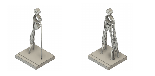
the chassis split by loading condition, each grown in Fusion 360 and merged into one print
169g
generative body
the printed structure; the reaction wheel, motors, batteries and boards add 481 g (paper, Table 1)
>15
safety factor
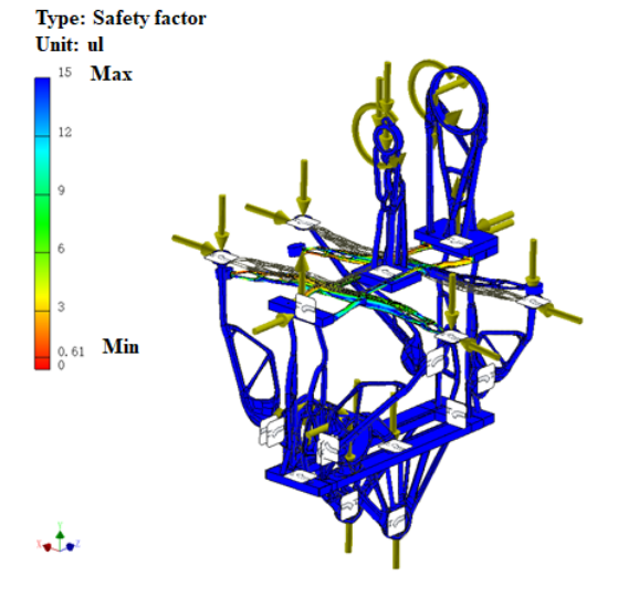
Inventor FEA on the merged body under the design loads (paper, Fig. 8); the design target was 2
0.69s vs 19.2s
pitch settling, paper
generative vs conventional in Simulink, 5° release, one PID set for both (Table 2)
−70%
bracket mass, re-run
the side support at 30 % fill keeps a safety factor of 45 (solid plate: 46); this page's topology optimisation
7.8 vs 9.0/s
unstable pole
how fast each chassis falls: lighter and higher centre of mass buys the controller time (re-run)

In one strip

Six stages of a bracket losing material until only a truss is left
1 · Carve

Loads in, brackets out

Each part gets a free-body diagram, preserved joints (green), forbidden regions (red) and a material list. The generative study subtracts material until only load paths are left, and the designer picks a solution on a mass against safety-factor chart.

Finite-element safety factor plot of the merged chassis, mostly blue (high safety factor)
2 · Verify

Mirror, merge, check

Generated parts are mirrored so they are stiff in all four bending directions, merged into one body, and checked in Inventor: safety factor above 15 everywhere under the loads of step 1. Then it is printed as a single piece.

Simulink traces of pitch, roll and top-point movement for the generative and conventional designs
3 · Balance

Same PID, two chassis

Pitch and travel are an inverted pendulum on the drive wheel; roll is a reaction-wheel pendulum. Three PID loops with one fixed gain set drive both chassis from a 5° tilt: the lighter, higher generative body settles in 0.69 s, the conventional one wanders for 19 s.

The robot, twice, in three dimensions

One drive wheel for pitch and travel, an aluminium reaction wheel on top for roll, three battery cells and the boards in between. The generative chassis carries them on lattice brackets; the conventional one on solid plates, assumed twice as heavy and with its centre of mass 3 cm lower, the two things the paper says about it. Both run the same three PID loops in your browser at 1 kHz. Push them, drop them from a tilt, scale the gains, add loop delay, and read the traces.

INTERACTIVE 3-D · TWO CHASSIS, ONE CONTROLLER

Push it, tilt it, re-tune it

push:
presets:
Loading…
Loading the scene…

Red is the generative chassis, blue the conventional. The gold band is the paper's 5 % settling band (0.25° of a 5° release). Motors are a 12 V geared brushed motor on the drive wheel and a direct-drive motor on the reaction wheel, both voltage-limited; the recoverable tilt (about 11°) is the reaction-wheel motor's stall torque, the same on both chassis.

Try the presets: with the paper's gains both balance (0.70 s vs 0.74 s). At ×1.5 the generative chassis still settles in 0.67 s while the conventional one chatters at the voltage limit for the whole run. With 35 ms of loop delay the generative chassis holds and the conventional one wanders half a metre.

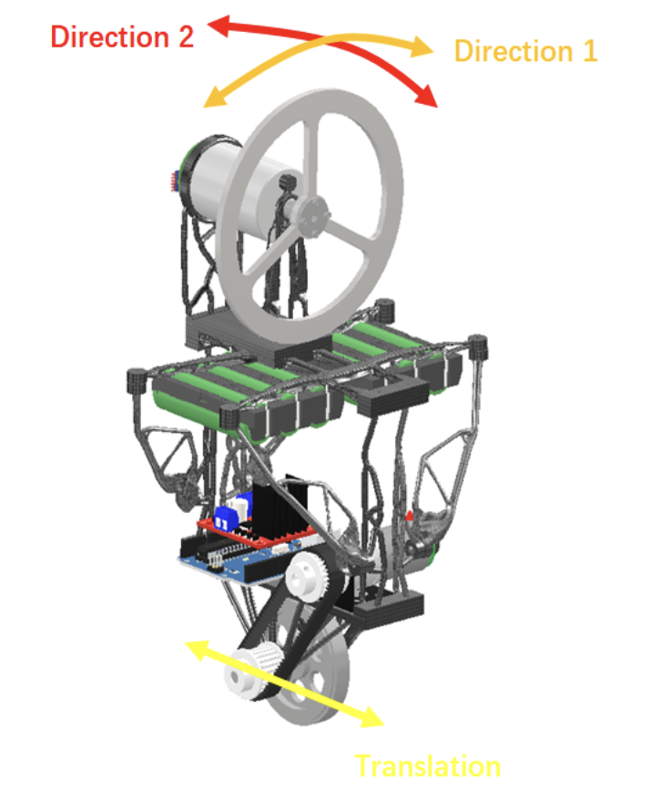
Render of the generative unicycle with the reaction wheel on top and the drive wheel below, with the two rotation directions and the translation direction marked
The paper's Fig. 9: the three degrees of freedom. Direction 1 is pitch, corrected by driving the bottom wheel under the body; direction 2 is roll, corrected by accelerating the reaction wheel; translation along the wheel is held by a third loop. The printed lattices are the generated brackets.

The printed prototype (13 s, phone clip): reaction wheel, drive wheel, an Arduino and driver boards on a printed body, balancing on a tile floor. The paper's outlook was to print the two bodies in Nylon and close the comparison on hardware.

The generative design pipeline, step by step

Generative design here means: tell the software where the loads go, what must stay, what must stay empty, which materials and processes are allowed, and let it grow candidate shapes; then choose among them. The paper walks the unicycle body through five steps.

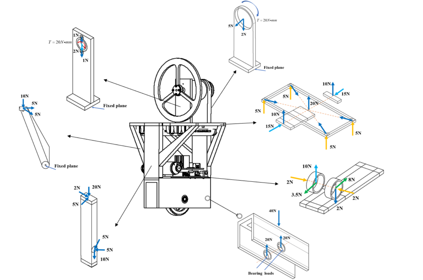
Free-body diagrams of the seven parts of the unicycle body
1

Force distribution

A simple reference model is split into seven parts by loading condition and each gets a free-body diagram from the masses of Table 1: reaction wheel and motor, drive motor, batteries, boards. Design safety factor 2.

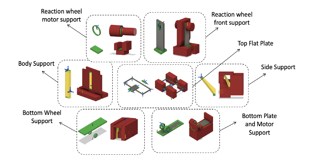
Fusion 360 generative design inputs for the seven parts: preserved geometry in green, obstacles in red, starting shapes in yellow
2

Preserve, forbid, seed

In the Fusion 360 Generative Design workspace: green is preserved (joints, grounds), red is an obstacle where nothing may grow, yellow is an optional starting shape that saves cloud time. Grey is the conventional part for reference.

Five generated outcomes of one study
3

Materials and process

No manufacturing constraint, so the studies range freely; Nylon, ABS, acrylic, resin, aluminium and titanium are allowed. The budget allowed Nylon SLS printing, so Nylon outcomes are what gets picked.

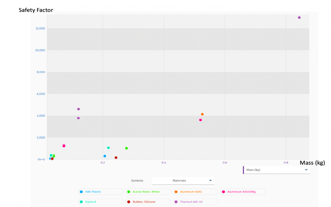
Safety factor against mass for the generated outcomes, coloured by material
4

Generate and pick

The cloud computes the outcomes; a safety factor against mass chart shows them by material, with a recommended one. The final part is the Nylon outcome nearest the recommendation.

A generated support before and after mirroring, stiff in all bending directions
5

Mirror and merge

Moment analysis was one-sided, so parts are mirrored twice for stiffness in all four bending directions, merged into one body, checked in Inventor (safety factor above 15) and printed in one piece.

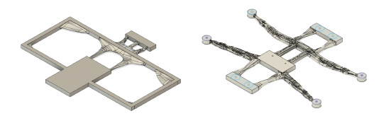
Two generated bottom plates: an over-constrained one that stayed almost solid and a minimally constrained one that became a slender cross
A lesson from the paper (Fig. 7): over-constraining kills the mass saving. With too many preserved regions the generated part stays close to the original; with the minimum, the bottom plate became a slender cross.

What the software is doing underneath. Fusion 360's generative design is a cloud service, but for a bracket under a static load its core is the classic problem of topology optimisation: distribute a fixed amount of material in a domain so that the part is as stiff as possible under the load, with preserved and forbidden regions as constraints. The playground below runs the textbook version of that algorithm (SIMP: penalised densities, a density filter, an optimality-criteria update) on the paper's three main brackets, in your browser, so you can watch the material subtraction of Fig. 3 happen and move the loads yourself.

The three time-lapses are the same algorithm run offline on finer grids, with a stress check afterwards: von Mises stress on the final layout under the design load, and the safety factor against Nylon's yield, so a mass against safety-factor chart like the paper's Fig. 5 falls out of the volume-fraction sweep.

SIDE SUPPORT

From a 30 % fog to a truss

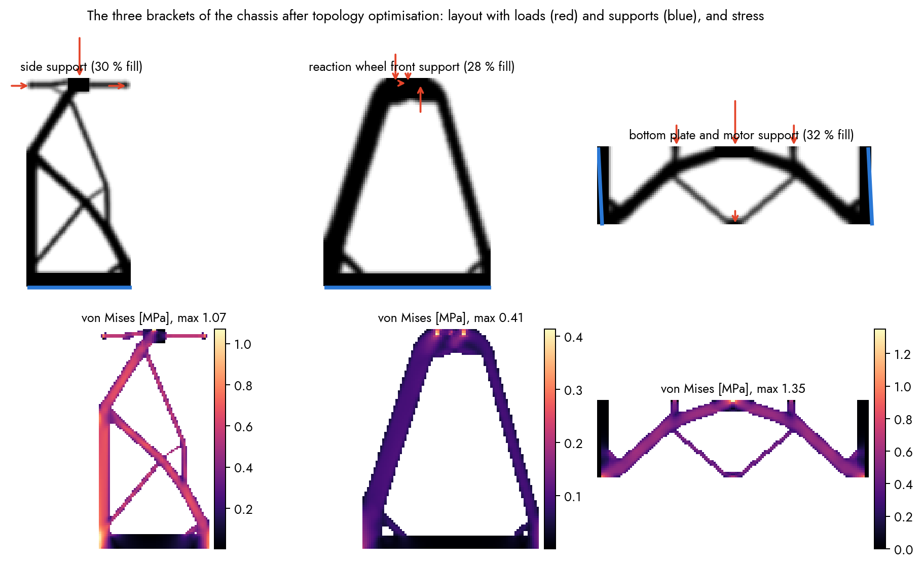
Fixed plane at the bottom, 10 N down from the top plate, 5 N sideways each way. 70 iterations; mass −70 %, safety factor 45 against 46 for the solid plate.

REACTION-WHEEL SUPPORT

A hollow A-frame

The bearing seat carries the wheel's weight, the motor torque as a couple and a sideways load. Mass −72 % at a safety factor above 100.

BOTTOM PLATE

An arch with a hanger

Both ends fixed, the motor in the middle, batteries either side, a bearing pull below: the plate becomes an arch and a V, the paper's slender cross seen from the side. Mass −68 %.

INTERACTIVE · TOPOLOGY OPTIMISATION IN THE BROWSER

Carve a bracket yourself

Pick one of the paper's brackets or a classic case, press Run, and watch the material go where the load paths are. Paint preserved regions (they stay solid, like the green joints in Fig. 2) and obstacles (nothing grows there, the red boxes), or move the load. Lower the target volume and read off the mass and the safety factor; the compliance curve shows the optimiser converging. Plane-stress finite elements, SIMP with penalty 3, solved matrix-free by conjugate gradients, all in JavaScript.

Loading…

fixed nodes   loads (arrows, N)   preserved   obstacle   ink = material. Element size 1.7 mm for the paper's parts; plate thickness 6 mm; Nylon PA12, yield 48 MPa. The safety factor is the yield stress over the largest von Mises stress on solid elements, a stress post-check on a stiffness-optimised layout, as in the paper's step 5.

The paper's Fig. 5, re-made. For each bracket the target volume is swept from 15 % to solid. Above about 30 % fill the safety factor stops improving: the extra material sits off the load paths. That knee is where generative design earns its mass saving, and it is where the paper's chosen outcomes sit.

The three brackets after topology optimisation with loads and supports, and their von Mises stress fields
The three brackets at their chosen fills, with loads (red) and supports (blue), and the stress on the final layout. Stresses are a fraction of a megapascal: at these loads the parts are far from yield, so the design is stiffness- and mass-driven, as the paper's safety factor above 15 also says.

Two pendulums, three PID loops

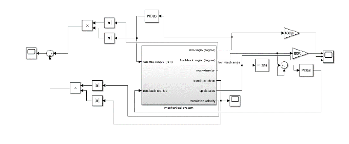
The paper splits the robot the way every reaction-wheel unicycle is split: pitch and travel are a wheeled inverted pendulum driven by the bottom wheel, and roll is a reaction-wheel pendulum pivoting about the ground contact line. With the generalised coordinates q = (θ₂, ϕ, θ₁, φ) of Eq. (3.1), reaction-wheel angle, roll, drive-wheel angle, pitch, and the Lagrangian L = E − U of Eqs. (3.3)–(3.5), the Euler–Lagrange equations give the motion; the paper's Eqs. (3.6)–(3.9) are those with the DC-motor torques substituted.

pitch: (Jb + m l²) φ̈ + m l cos φ ẍ − m g l sin φ = −τ₁  ·  (M + Jw/r²) ẍ + m l cos φ φ̈ − m l φ̇² sin φ = τ₁ / r
roll: Jp ρ̈ − Mt g lb sin ρ = −τ₂  ·  J₂ (ρ̈ + θ̈₂) = τ₂
motors: τ = KT (u − KE ω) / R  ·  the paper's KE·60/(2π) is KE in V per rpm

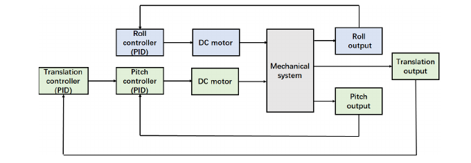
The re-run keeps the wheel/body coupling terms of the pitch subsystem (m l cos φ on both rows), which the paper's Eq. (3.8)–(3.9) drop; their small-angle, uncoupled form is the special case. Three PID loops close the system exactly as in Fig. 10: roll on the reaction-wheel motor, pitch and translation summed onto the drive motor, with one gain set for both chassis. The re-run adds a small reaction-wheel speed term to the roll loop (the standard fix for wheel-speed drift) and drops the roll integrator; the pitch loop keeps its integrator with anti-windup.

u₁ = Kp φ + Kd φ̇ + Ki ∫φ + Kx x + Kdx ẋ  ·  u₂ = Kp,ρ ρ + Kd,ρ ρ̇ + Kw θ̇₂  ·  |u| ≤ 11.1 V, 200 Hz, RK4 at 1 kHz

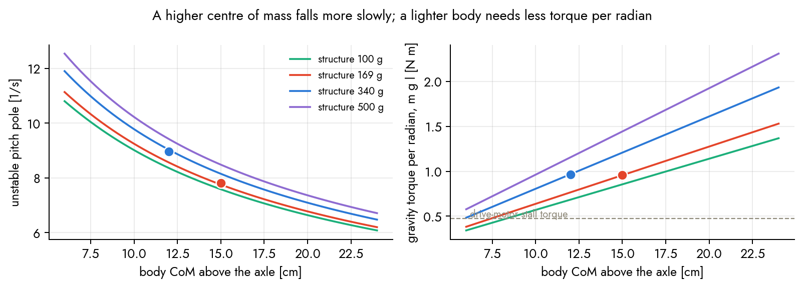
Why the chassis matters to the controller. Linearised about upright, the pitch subsystem has one unstable pole at roughly √(g / leff): the higher the centre of mass, the slower the fall. A lighter body also needs less torque per radian of lean (m g l). Generative design moved the chassis from 820 g with the centre of mass 12 cm above the axle to 650 g at 15 cm: from a 9.0 /s pole to a 7.8 /s one, at nearly the same m g l. That is the whole physical effect the sweeps below quantify.

Block diagram: translation and pitch PID controllers feeding one DC motor, a roll PID feeding another, a mechanical system block with roll, pitch and translation outputs
The paper's control diagram (Fig. 10). Three PID blocks, two motors, one mechanical system: translation and pitch share the drive motor.
Unstable pitch pole and gravity torque per radian against centre-of-mass height for four structure masses
The plant the controller sees. Left: the unstable pitch pole falls with the centre-of-mass height and barely depends on the structure mass. Right: m g l, the torque a radian of lean costs, against the drive motor's 0.48 N m stall torque. The dots are the two chassis.
Simulink control layer
The paper's Simulink control layer (Fig. 11).
Simulink Simscape mechanical layer
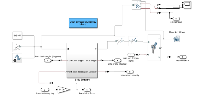
Simscape Multibody mechanical layer (Fig. 12), with the CAD bodies imported.

The comparison, re-run

The paper's Simulink/Simscape model and the Fusion 360 files are not available, so the comparison is re-run with the equations above, the component masses of Table 1, and estimates for what the paper does not give (wheel radius, inertias, motor constants, the conventional body's mass), all stated in the report. Same protocol: both chassis released from 5° pitch and 5° roll, one PID set, settling time in the paper's 5 % band, the top-point excursion, and the electrical power of the two motors.

metricgenerative, paperconventional, papergenerative, re-runconventional, re-rungenerative, ×1.5 gainsconventional, ×1.5 gains
pitch settling time, 5 % band [s]0.68819.210.700.740.67none in 12 s (limit cycle)
roll settling time [s]0.0600.0601.271.271.271.27
peak top-point excursion [cm]9.235.63.12.93.14.4
mean electrical power over the run [W]340 (their units)3480.530.480.4544
peak electrical power [W]2.76e6 (their units)2.98e6126126126126
energy to recover [J]——5.44.95.4528 (12 s)
unstable pitch pole [1/s]——7.89.07.89.0
body mass / CoM above the axle169 g body, "higher""heavier, lower"650 g / 15 cm821 g / 12 cm650 g / 15 cm821 g / 12 cm
← swipe the table →

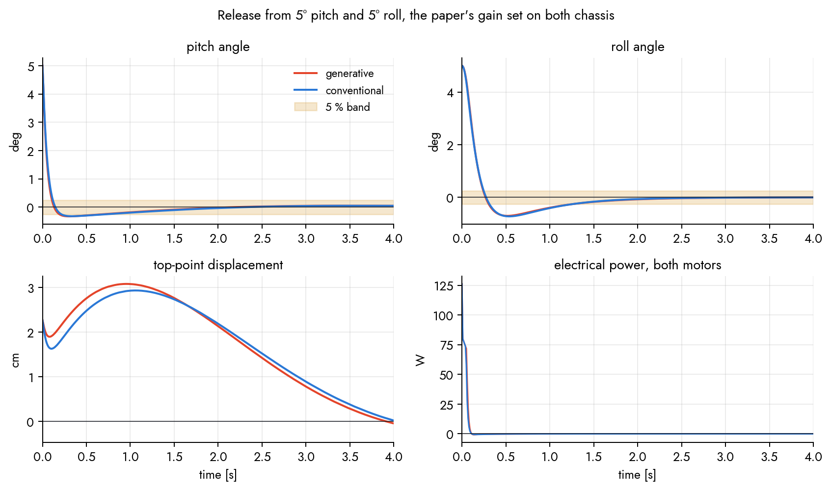
The paper's roll settled in 0.06 s and its power numbers are unscaled Simulink signals, so those columns are shown for the record only. The re-run's roll takes 1.3 s because the reaction-wheel motor saturates at 11 V for the first 0.2 s: with a realistic motor, roll is the slow axis. The pitch settling of the generative chassis with the paper's gains, 0.70 s, matches the paper's 0.69 s; the difference is what the conventional chassis does.

With the paper's gains, both chassis balance and the traces nearly overlap: the conventional one is 40 ms slower in pitch and reaches the same peak power, the voltage limit. The difference the paper reports is not visible here. It appears when the gain set moves towards the edge of what the conventional chassis tolerates:

The same gain set scaled ×1.5. The generative chassis settles in 0.67 s; the conventional one never settles within the 12 s run: its drive voltage sits at the ±11 V limits 81 % of the time, its pitch buzzes within ±0.45°, the wheel wanders over 8 cm, and it burns 528 J against 5 J. Inside one chassis' margin, outside the other's: that is the 0.69 s against 19 s of the paper's Table 2 in this model.

THE PAPER'S GAINS

Same gains, both balance

5° pitch and 5° roll release. Pitch in 0.70 s against 0.74 s; roll in 1.3 s on both, limited by the reaction-wheel motor.

GAINS ×1.5

At the edge of the margin

The generative chassis settles; the conventional one chatters at the voltage limit and drifts. The drive-voltage trace is the tell.

PUSHED TWICE

Kicks at 1 s and 4 s

1.2 rad/s on both axes, the largest push either chassis survives with these motors: the reaction wheel's stall torque, not the chassis, sets the limit.

35 MS LOOP DELAY

A sluggish sensor chain

The paper's gains with 35 ms between measurement and voltage: the generative chassis holds, the conventional one wanders. Both fall at 45 ms and 40 ms.

1

The chassis is a plant, not a tune

With one fixed gain set the two chassis behave nearly the same until the set approaches the conventional chassis' limits. The paper's 0.69 s against 19 s is what one gain set looks like when it sits inside one chassis' margin and outside the other's.

2

A higher centre of mass buys time

The unstable pole went from 9.0 /s to 7.8 /s. In the sweeps that is 10 % more gain margin, 5 ms more loop delay and a 25 % slower control loop before the fall, at the same motors. Mass alone changes little: m g l is nearly equal for the two.

3

What the motors set, the chassis cannot move

The largest recoverable tilt (11°) and push (1.25 rad/s) are identical for both: the reaction-wheel stall torque against M g lb sin ρ. Peak power is the voltage limit on both. Energy per 5° recovery is 5 J either way.

What the chassis buys you: the sweeps

One simulation per point, deterministic, from the same scripts. Red is the generative chassis, blue the conventional; a cross marks a fall.

Gain margin. Scaling the paper's pitch and position gains together: both improve until 1.375×, where the conventional chassis breaks into a limit cycle; the generative one holds to 1.5×. Below 0.5× both are simply slower.

Energy against the gain scale. Inside the margin a 5° recovery costs 5 J; the limit cycle costs a hundred times that, most of it heating the drive motor's winding at the voltage limit.

Loop delay. Peak top-point excursion as a pure delay is added between measurement and voltage. The conventional chassis starts wandering at 20 ms and falls at 40 ms; the generative one at 30 ms and 45 ms.

Control period. The same gains with a slower controller: the conventional chassis falls at a 40 ms period, the generative one at 50 ms. A slower fall tolerates a slower loop.

Initial tilt. Energy to recover grows with the tilt; both chassis fall from 12°, where the reaction-wheel motor can no longer out-torque gravity in roll. The generative chassis costs slightly more energy per recovery: its centre of mass is higher, so a degree of lean is more potential energy.

Push at 1 s. Peak pitch after an impulsive kick on both axes; both survive up to 1.25 rad/s and fall at 1.5. The generative chassis swings 20 % further for the same kick (lighter, higher) and recovers in the same time.

THE MAP · STRUCTURE MASS × CENTRE OF MASS

Where generative design moved the chassis

72 chassis on a grid of structure mass and centre-of-mass height, all with the paper's gains. The white circles are the two chassis; the arrow is the move generative design made. Low centres of mass fall with these gains no matter the mass; the conventional chassis sits one row above that edge, the generative one three.

If each chassis gets its own tune. LQR on the linearised plant with the same weights for both, mapped onto the paper's three-loop structure: the two settle in 0.80 s and 0.80 s (pitch), 0.96 s and 0.91 s (roll). Retuned, the chassis difference nearly vanishes; what remains is the margin above.

Pitch, roll, top-point displacement and power traces for both chassis with the paper's gains
The nominal release, all four traces (also in the report as vector figures, with the full sweeps).

The explainer

Seventy-two seconds: the robot and its three degrees of freedom, the five-step pipeline with the topology optimisation running, the mass against safety-factor chart, the two pendulums released with the motors off, the nominal and the edge comparisons, the sweeps, the printed prototype, and what this re-run can and cannot claim.

Reproduce

Everything on this page comes from one small Python package and four scripts; nothing is random, so there are no seeds. The package holds the two chassis, the motors, the dynamics with RK4 and the three PID loops, the metrics, the linearisation with an LQR helper, and the SIMP topology optimiser with the stress check. The scripts run the sweeps in parallel, draw the figures and the results JSON the plots above read, render the videos with a small software rasteriser, and build the report.

# Unicycle/experiments
python -m pytest -q tests                # energy conservation, linearisation vs finite differences, closed-loop, settling, topopt
python run_study.py control              # 2 x main + gain / delay / rate / tilt / push / friction sweeps + the 72-chassis grid -> out/study.json
python run_study.py topopt               # three brackets x ten volume fractions, time-lapse frames -> out/topopt.{json,npz}
python make_figures.py                   # docs/figures/*.pdf, site PNGs, assets/data/unicycle_results.json, docs/numbers.tex
python make_videos.py --which all        # teaser, explainer, comparisons, time-lapses, thumb -> assets/videos/unicycle_*.mp4
cd ../docs && make                       # unicycle.pdf, the technical report

Files. unicycle/params.py (Chassis, Motor, Gains and every estimate in one place), model.py (Unicycle, simulate, metrics, linearise, lqr), topopt.py (LoadCase, topopt, stress_check, the three brackets); render.py is the rasteriser. The browser twins are assets/js/unicycle_sim.js (the same model, line for line), unicycle_scene3d.js (three.js), unicycle_topopt.js (SIMP with a matrix-free conjugate-gradient solve) and unicycle_plots.js.

Assumptions you can change. Drive wheel 70 mm, 40 g; reaction wheel 120 mm ring, 85 % of m r²; body radius of gyration 0.6 of the CoM height; a 12 V geared drive motor (0.48 N m stall) and a 0.33 N m direct-drive reaction-wheel motor; the conventional structure at twice the generative mass with the centre of mass 3 cm lower. The grid sweep shows how the conclusions move with the last two.

Technical report (PDF): the derivations, the parameter table, every figure with its numbers, and the limitations.

Credits

Generative Design for Self-balancing Unicycle Robot in Additive Manufacturing. Jiaqi Chen (Tongji University), Qilong Cheng (University of Toronto) and Mengrui Han (Beijing University of Technology); the first two authors contributed equally. International Conference on Automation Control, Algorithm, and Intelligent Bionics (ACAIB 2022), Proc. SPIE 12253, 122530A. doi:10.1117/12.2639454.

Figures 1 to 14 shown on this page are the paper's. The 3-D twins, the topology-optimisation playground, the time-lapses, the comparison videos, the sweeps and the report are mine, built from the paper's equations and Table 1 with the estimates stated above; the Simulink and Fusion 360 files of the original study were not available for this re-run. The prototype clip is from the project.