Mechatronics ◆ MIE444 ◆ University of Toronto ◆ 2022

Four ultrasonics and a rotation

A 170 mm robot has to find itself in an eight-by-four maze it has never seen from the inside, fetch a wooden block, and deliver it — in five minutes, with no camera, no odometry it trusts, and, at first, no compass. It solves this by reading the four walls around it as a four-bit number and rotating that number until it matches the map. Below you can drop it somewhere at random and watch every place it might be disappear, one move at a time.

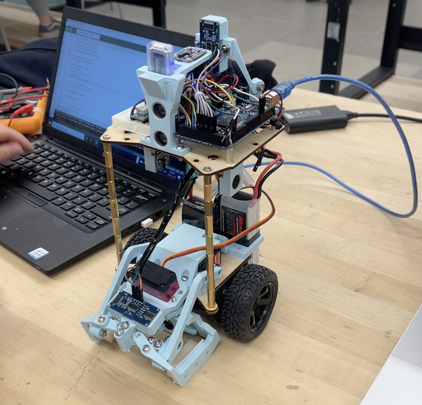
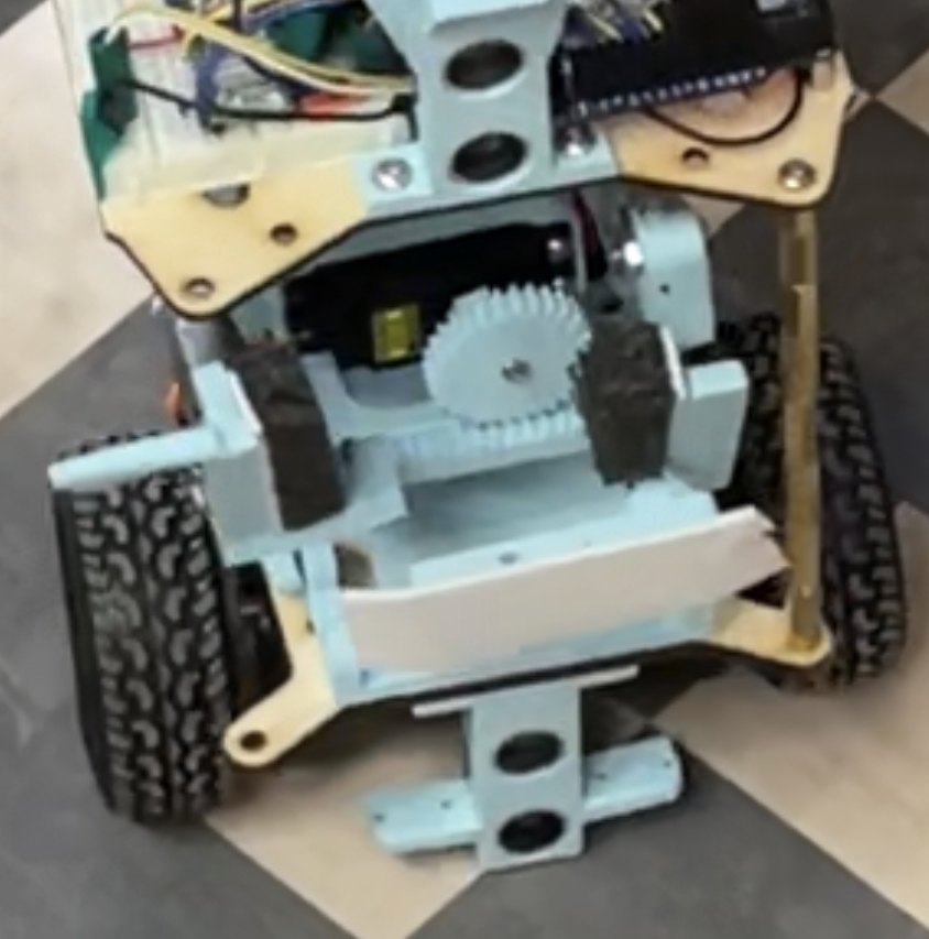
The real thing, in the Myhal Centre maze: gripper down, block ahead, wooden walls at twelve inches on a side. It ran the maze in three minutes on its first trial at the second milestone, without a practice run.

Ultrasonics4
Bits per tile4
Free tiles24
Diameter170mm

Find yourself

The robot has been put down somewhere in the maze, facing some direction, and it does not know either. All it can read is whether there is a wall in front of it, behind it, and to each side — the four ultrasonics, and nothing else. Every tile shaded below is a tile it could still be on; every arrow is a heading still consistent with everything it has seen. Drive it one tile and watch them go.

The maze, and everywhere it might be

Small grey numbers are each tile's own wall code, for reference — the robot cannot see them. Hatched tiles are blocked. Arrow keys drive.

Reading 0 — binary 0000, in the robot's own frame.

The highlighted key is the move that cuts the candidate set fastest.

Candidates0
Tiles0
Moves0
Of96

A tile is four bits, and a turn is a bit rotation

The maze is a grid of 12-inch tiles. What the robot can measure about the tile it is standing on is exactly four booleans — wall or no wall, on each side — so a tile is a number from 0 to 15. The map of the whole maze is 32 such numbers, hardcoded.

The design decision that makes the rest work is the order of those four bits. They are assigned going around the tile — north, west, south, east — rather than in any arbitrary order:

code = 1·[N closed] + 2·[W closed] + 4·[S closed] + 8·[E closed]

Because the bits go around the tile, turning the robot 90° is a cyclic rotation of the four bits. A robot facing an unknown direction does not have to enumerate four different geometries; it reads one number, and the four hypotheses are that number rotated 0, 1, 2 or 3 places. In MATLAB that is one call to bitror. The whole orientation problem collapses into a rotate instruction.

Localization is then a set intersection, and nothing more. Start with all 96 states — 24 free tiles × 4 headings. Keep the ones whose rotated code matches the reading. Drive one tile, push every surviving candidate along the same body-relative move, drop the ones that would have hit a wall, and intersect with the new reading. Repeat until one survives.

What makes this a real problem rather than a formality is how little a four-bit reading tells you.
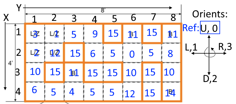
The maze as a 4 by 8 grid of decimal wall codes, with blocked tiles marked 15.
The map the robot carries, from Figure 2.2-1 of the report: 4 rows × 8 columns, each tile written as its decimal wall code, 15 meaning blocked. The 2 × 2 block at the top left is the loading zone; the tiles marked B are the four drop-off zones. Every number on this page was computed from this map, transcribed into assets/data/mie444_maze.json.
Rotation classLooks likeTiles
{0}open on all four sides1
{1, 2, 4, 8}one wall4
{3, 6, 12, 9}a corner6
{5, 10}a corridor9
{7, 14, 13, 11}a dead end4

Sixteen codes, but they fall into six classes under rotation — and one of those, 15, only ever marks a blocked tile. So a robot that does not know which way it is facing has an alphabet of five symbols for 24 tiles. Nine of those tiles are corridors, and a corridor looks identical from both ends.

1

The one tile you can identify is the one that tells you nothing

The report singles out the four-way intersection — the only tile in the maze with code 0 — as the one place a single reading pins you down. That is true of the tile: code 0 appears exactly once on the map, so reading 0 means you are standing on it.

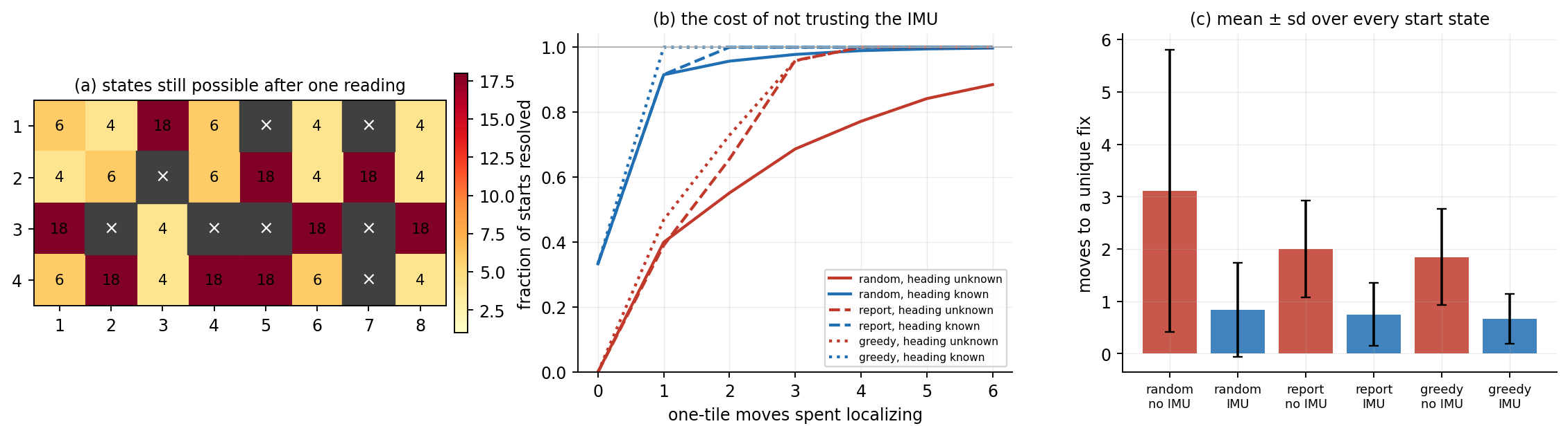
But code 0 is also the one code that is unchanged by rotation. Standing there, all four headings remain consistent, and a robot that knows where it is but not which way it faces cannot take a single step of its route. Sweeping all 96 states, no state is resolved by one reading: the smallest candidate set after a first look is 4, the largest is 18, and the average is 9.8. The intersection is not the middle of the algorithm, it is the whole of it.

(On the printed map that intersection sits at row 2, column 6; the report's text calls it (1, 6), which does not match its own worked example two paragraphs later — that one, "a code 10 above a code 12", lands correctly at row 3, column 6.)
What the compass was worth

Halfway through the project the team changed their minds about the IMU. The original design refused to trust it — a magnetometer indoors, near motors, is not a compass — so the robot had to recover its heading from ultrasonics alone. Later they found that disabling the magnetometer and calibrating the gyro at power-up gave better than ±30°, which is enough to pick out an orthogonal direction, and they let the algorithm use it. The report's claim is that this took localization "from up to 3 moves down to at most a single 1-tile movement".

That claim is checkable, and the map is small enough to check it exhaustively rather than by sampling. scripts/tools/mie444_localize.py runs the belief-set localizer from every one of the 96 possible start states, under three move-selection rules and both knowledge settings.

Three panels: a map of how many states survive one reading, cumulative distributions of moves to localize, and mean moves by policy.
Every start state, exhaustively. (a) The worst case at each tile: how many of the 96 states still fit after a single reading. Corridors are the dark tiles — 18 candidates each. (b) Fraction of starts resolved within a given number of one-tile moves; blue is heading known, red unknown. (c) Mean ± sd across all starts. Random-walk figures are averaged over 400 trials per start; the greedy rule is deterministic.
Move ruleHeadingMean movesWorst caseDone in ≤ 1 move
Randomunknown3.11never resolved40 %
Prefer straight, no reversalunknown2.00439 %
Greedy (minimise expected candidates)unknown1.84447 %
Randomknown0.84never resolved92 %
Prefer straight, no reversalknown0.75292 %
Greedy (minimise expected candidates)known0.671100 %
2

The report's claim holds exactly, and it is the strongest form of it

With the heading known and a sensible choice of which way to drive, every one of the 96 start states resolves in at most one move, mean 0.67 — which is precisely "at most a single 1-tile movement", not approximately. Without the heading, the same rule needs 1.84 moves on average and up to 4 in the worst case. The report remembered "up to 3"; on this map it is 4, from the corridor tiles.

So the IMU was worth about 1.2 tile-moves per localization, and it removed the tail entirely. In a five-minute run where the robot re-localizes whenever its wall reading disagrees with its believed position, that tail is the part that costs you the contest — not the average.

3

The team was right that the path rule barely matters — but only once you have the compass

The report says the scheme for choosing which way to drive is "a predefined scheme … but the impact is very small even compared to a random choice". Measured: with the heading known, informed choice beats a random walk by 0.17 moves (0.67 vs 0.84) — negligible, exactly as claimed.

Without the heading it is not negligible at all: 1.84 versus 3.11, a 41 % saving, and a random walk fails to resolve some starts within a dozen moves while the informed rule never exceeds four. The instinct was right for the robot they ended up shipping and wrong for the one they started with. It is a good illustration of how a sensor decision quietly changes which software decisions matter.

Assume it never drives straight

All of the above assumes the robot can move exactly one tile and end up square in the next one. It cannot, and the report's stated design principle is unusually blunt about it: distrust the physical robot and increase trust as needed. Assume the motors desync, assume friction is asymmetric, assume nothing is straight.

The team considered closing a PID loop on heading and rejected it as too complex for the schedule. What they built instead is geometric and open-loop-per-step: a tile crossing is broken into three-inch increments, and each increment corrects one error.

Before each increment, the side ultrasonics give the distance to the reference wall — the shorter of the two readings, because ultrasonic error grows with range, or both together in a corridor. Comparing that to the ideal centre-lane distance gives a lateral offset, and the robot turns by θ, drives the increment diagonally, and turns back by −θ, so it arrives forward by the step and sideways by the correction.

After the increment, it measures the side distance again. If the heading error α were zero, the lateral offset would now be zero. It is not, and the discrepancy is exactly what α produces — so α is recovered from the residual and corrected by rotating.

lateral error fixed before the step · heading error fixed after it — each increment leaves the robot straighter than it found it

It is a dead-reckoning-free controller: nothing accumulates, because every three inches the walls tell it the truth again. The report's own summary is that the robot "perfectly travels without hitting any object", and the measured outcome — a clean maze run on the first attempt at milestone two — supports it.

The failure mode is where the reference disappears. Around some corners, and in the middle of the run between (1, 4) and (2, 4), the guiding wall switches sides mid-step, and wall-following faithfully follows it around the corner. The fix is not a better controller: it is a hardcoded list of positions where wall-following is switched off for part of a movement. Which means the geometry module depends on the localization module, while localization depends on the robot being able to drive straight — a circular dependency the report calls out explicitly as the thing that made integration delicate.

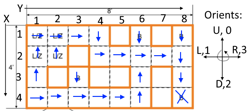
The maze with an arrow in each tile pointing toward the next tile on the route to the bottom-right drop-off.
Navigation, once localized, is a lookup table: one arrow per tile giving the next tile on the way to a given drop-off. The robot never holds a route, only its current cell and the next step — so a mid-run re-localization costs nothing to recover from. Figure 2.2-2 of the report.
4

Two identical sensors, same surface, different answers

Block detection was meant to be a difference of two forward ultrasonics — one low, one high. Off-normal, an ultrasonic reads sensibly to about 30° and then goes chaotic, and the team knew that. Their assumption was that two sensors looking at the same surface, at the same range and the same angle, would at least be chaotic together — so a disagreement would mean one of them had found the block.

They did not. Measuring the same wall at the same angle, the two sensors returned drastically different values, and the whole differencing scheme fell over. The gripper was finished late enough that this only surfaced at the competition, and the recovery was a brute-force sweep: drive a fixed search pattern through the loading zone until the downward-facing sensor sees the block underneath the gripper.

The clean lesson is in the report's own recommendation — a time-of-flight sensor instead, which does not have an angle-of-incidence failure mode in the first place. The sharper one is about what a shared failure mode is: correlated noise is a property of the noise, not of the geometry, and two parts from the same bin are not two samples of the same random variable.

Three robots in one semester

The software above was written and tested in a MATLAB simulator for weeks before any of it ran on hardware, which is why it is so suspicious of the hardware. That turned out to be the correct posture, because the first robot did not survive its first competition.

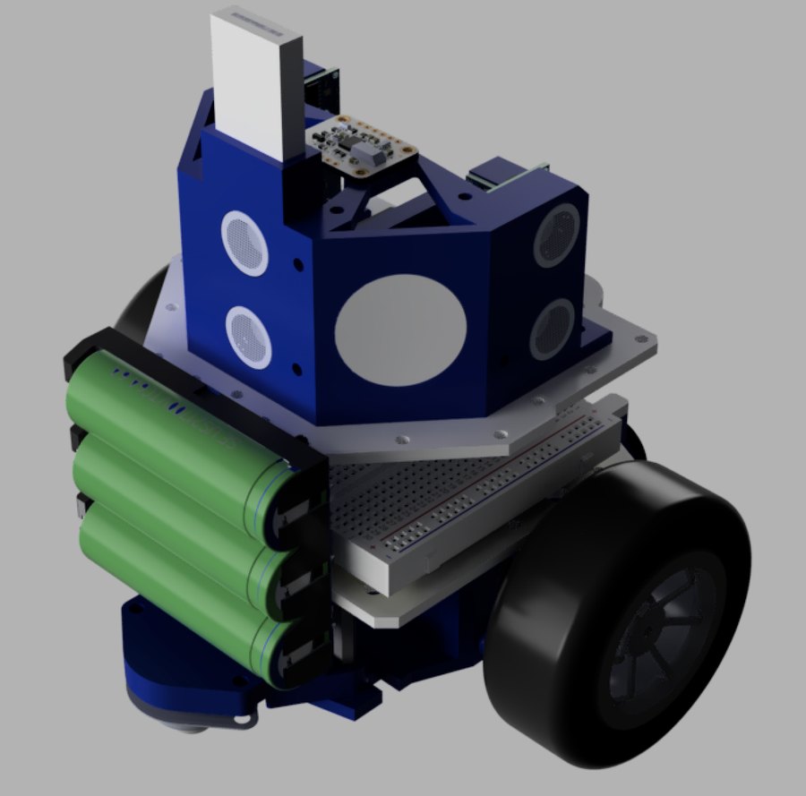
CAD render of the first robot: a compact blue stack with the battery as a structural member.
Design one. Compact, 205 mm across, each layer supported by the one below — the battery pack is a structural member. Assembly was impossible in the intended order and the wiring became unreachable once the battery was in.
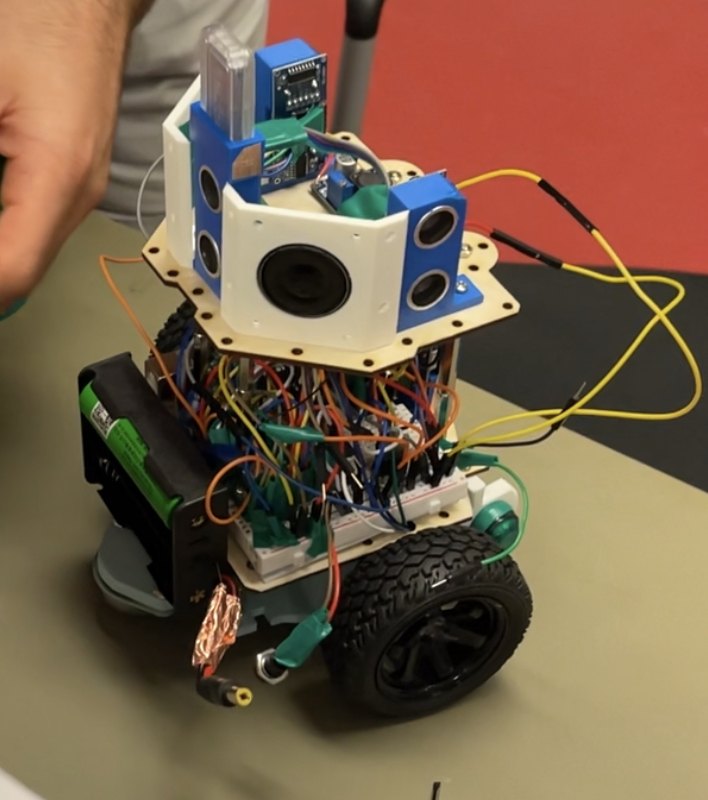
Photograph of the first robot, wires everywhere.
As built. Wires that would not seat in the breadboard were held with superglue, which conducts once it warms. Hours before the first milestone it shorted 12 V to ground and took out both motor drivers and most of the ultrasonics.
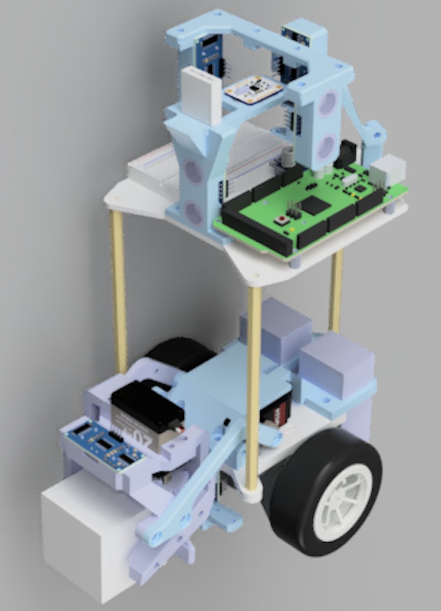
CAD render of the redesigned robot: taller, modular, wiring on the top deck.
Design two. Taller instead of wider, assembled deck by deck, all wiring moved to the top layer. Diameter 205 → 170 mm, and in a maze of 12-inch tiles those 35 mm were the single biggest competitive advantage the team had.
Photograph of the final robot on a bench next to a laptop.
And as built. Ultrasonics on all four faces of the sensor tower, IMU on top, Arduino Mega and one breadboard on the upper deck, gripper folded under the nose. Every wire reachable without taking anything apart — which was the entire point of the redesign.
Photograph of the rack-and-pinion gripper.
The gripper, second attempt. Two 3D-printed four-bar linkages on M3 screws rather than bearings: friction, backlash, and parts that worked loose. Replaced by a rack and pinion driven straight off the servo — fewer parts, same torque, and it retracts inside the body so it costs no diameter.

The electronics ceiling was pin count, not compute

The first build put every ultrasonic on a shared echo pin to save I/O on an Arduino Uno. Sharing serialised the readings and let the echoes interfere; a diode per pin did not fix it. The Uno also had no room for the MOSFETs the speakers and high-voltage LEDs needed, each of which costs another digital pin.

The fix was to stop economising: an Arduino Mega, one trigger and one echo pin per sensor, and the decorative outputs deleted. The wiring then fitted on a single breadboard and needed no further modification for the rest of the project. It is the same ceiling the LED cube ran into — I/O and interrupt budget, not clock speed.

Two halves that barely know about each other

The Arduino is deliberately stupid. It accepts primitives over Bluetooth — read the left ultrasonic, turn this many degrees — and answers when done. Everything above that lives in MATLAB on a laptop: wall-following, localization, navigation, block handling.

The payoff is that the simulator speaks the same primitives, so the same MATLAB runs in simulation and on the robot with nothing swapped. That is why weeks of untested code worked on contact with hardware, and it is the same sim-and-real-share-the-logic split I have used on every project since.

BuiltChanged, and why
205 mm diameter→ 170 mm; clearance in a 12-inch maze
Battery as structure→ modular decks; assembly and access
Superglued wiring→ properly seated; the glue conducts hot
Arduino Uno→ Mega; pins, not speed
Shared ultrasonic echo pin→ one trig/echo each; interference
Four-bar linkage gripper→ rack and pinion; rigidity, part count
Ultrasonic block sensing→ recommended time-of-flight (VL6180)
Distrust the IMU→ trust it, gyro-only; worth 1.2 moves
!

How it actually went

Milestone one: not attempted. The short happened hours before the slot; the team submitted the working simulation instead.

Milestone two: the redesigned robot completed the maze on its first trial in three minutes, faster than expected, helped by a starting tile it could localize within.

Milestone three: the gripper snapped minutes before the first trial and was epoxied back together. The block was picked up successfully — better than expected, given the block-finding code had never run in the physical maze — then dropped after leaving the loading zone because the servos jittered. The robot carried on to the drop-off anyway. On the second trial, a change made for clearance (raise the gripper before turning) backfired and it set the gripper down onto the block; once that was moved aside it picked up and delivered in about four minutes with no further intervention.

The report's own conclusion is a scheduling one, and it is the right one: every failure above traces to hardware arriving too late to test the software against.

Credits

MIE444: Mechatronics Principles at the University of Toronto, December 2022. Group 1: Karim Mansour, Max Mizrahi, Jesse Chudnow and Qilong Cheng. The robot, the MATLAB control stack, the Arduino firmware and both mechanical designs are the team's course project.

The belief-set localizer on this page, the exhaustive sweep behind the figure and the table, and the browser sandbox were written afterwards, from the report's description of the algorithm and its printed map. They are a re-implementation for analysis, not the code that ran on the robot — the original MATLAB and Arduino sources are not in my possession.